Friday, December 15, 2006
koro.net


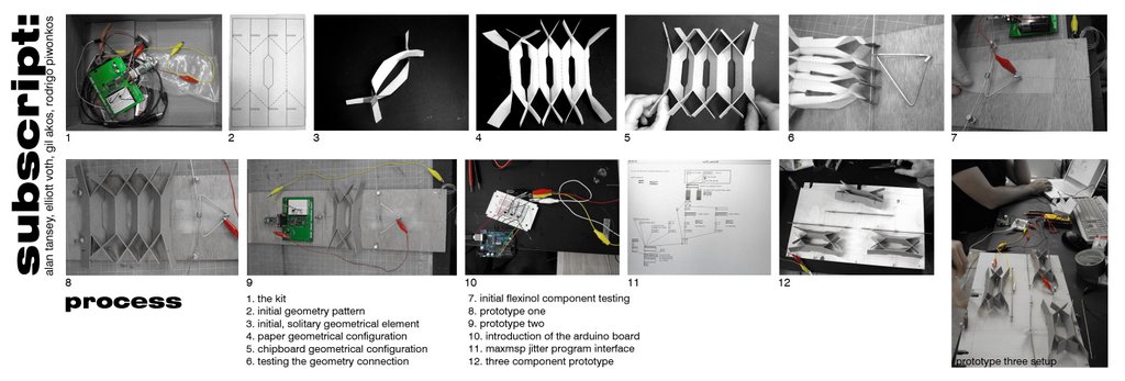
subscript final boards
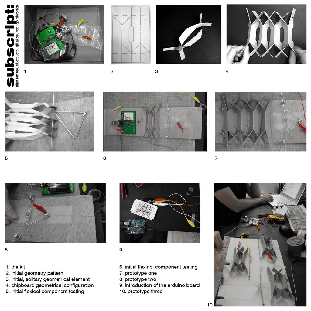
first prototypes exploring arduino and flexinol capabilities

multiplying the arduino output and studying movements for output
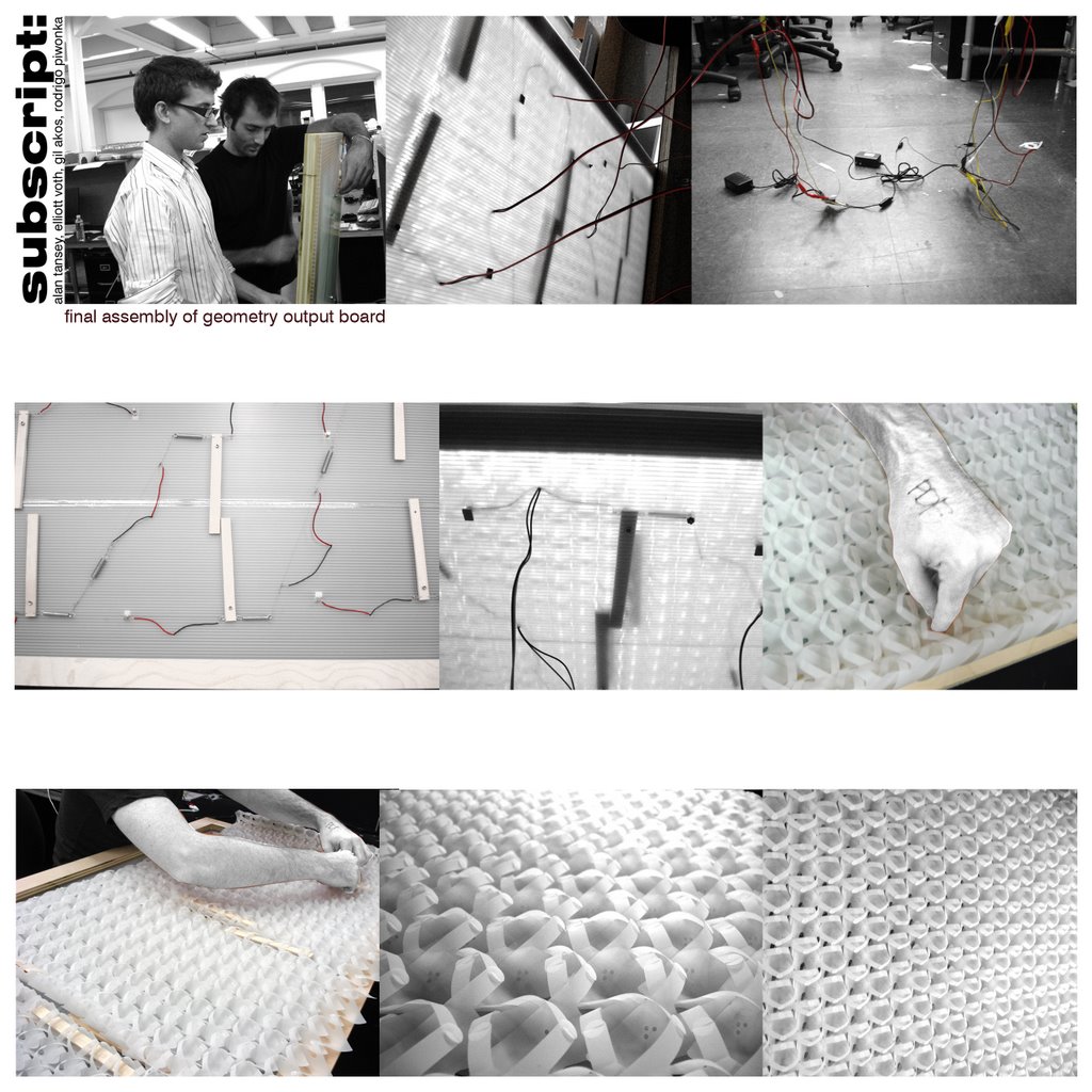
the final assembly of the geotmetry output board. the lever arms move behind the assembled paper geometry, which in turn, are affected.
subscript final geometry in motion
subscript lever arm videos
Thursday, December 14, 2006
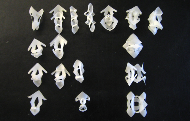
subscript geometry studies


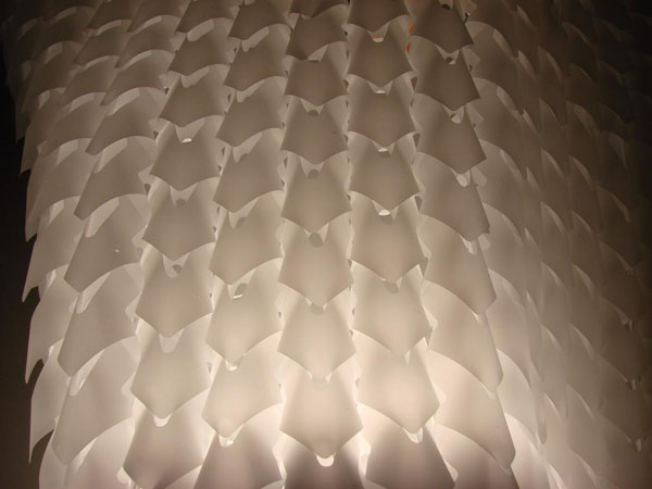

subscript movement studies
Monday, November 13, 2006
group 9 / Richard, Yen
+ Input component
motion sensor.
+ Processing component
basic stamp.
+ Output component
flexinaol wire.
+ Scale of a single "module" if you have one
pendant light fixture.
+ Number of modules you will create
1 prototype.
+ Siting (vertical, horizontal, indoor, outdoor, in a quiet environment, etc.)
indoor hanging from ceiling.
+ The "twist" of the project
using minimum movement create maximum enviornmental change throught light/shadow.
+ Vendors of all materials you will have to buy
Paper
parallax / motion Sensor.
dynalloy / flexinol.
+ List of technical issues and tests you will have to conduct in the
next five weeks
the tension of the flexinal wire.
how to control the open and close of the tube.
We reconsider the problems that came to us during the process. One of the biggest one is the friction of material. We choose plastic tubes to be our cells but they do not perform as we thought. They couldn't form a effective back and force movement. The original idea is to use the minimum input to achieve maximum output. We disign some movement which motivated by just a few cells.
Another big issue is the tension oh the flexinol wire. We couldn't come out a way to maintain the tension. Once it lose the tension, it will become less effective, even zero offset.
Now we adjust a little since one of us drop this class. We keep the basic idea of using little movement to achieve maximum performance. We change the material from plastic tubes to paper and the destination is to build a light fixture which can adjust by the sensors to create some relative effect from human movement.
Tuesday, November 07, 2006
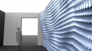
_subscript : cellular symphonic
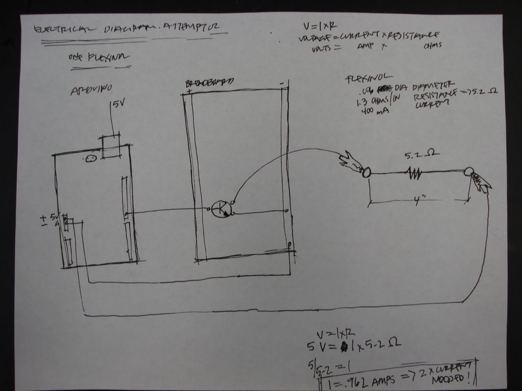
warning! rendering/diagrams below. dont worry, its constructive...


Tuesday, October 31, 2006
REFERENCE: Colour by Numbers: Cell Phone Control of Tower Lighting
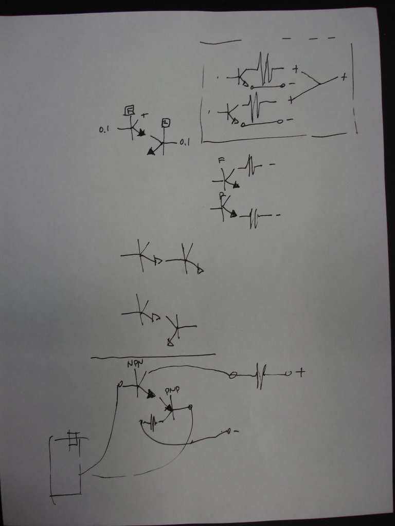
Cush_diagrams

subscript circuit explorations


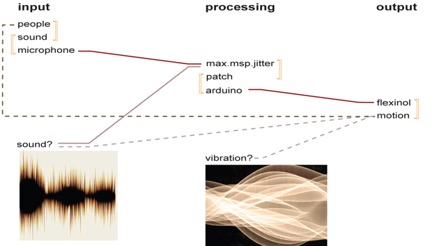
_subscript max.msp.jitter patch

Monday, October 30, 2006
_subscript differential motion
Group 9_Kirk+Yen+Richard_testing of output
first_testing_of_output
constrain_by_outside_force
testing_other_material
experiment_of other_possible_movement
constrain_by_outside_force
testing_other_material
experiment_of other_possible_movement
Saturday, October 21, 2006
INSPIRATION
INSPIRATION
Japanese Train Riders Power Their Own Subway Commutes
http://www.poptech.org/blog/2006/08/japanese-train-riders-power-their-own.html
http://www.poptech.org/blog/2006/08/japanese-train-riders-power-their-own.html
Thursday, October 19, 2006
INSPIRATION: Hussein Chalayan 2007 S/S Collection
INSPIRATION: Hussein Chalayan 2007 S/S Collection
Tuesday, October 17, 2006
video- attempt at three simultaneous outputs through arduino
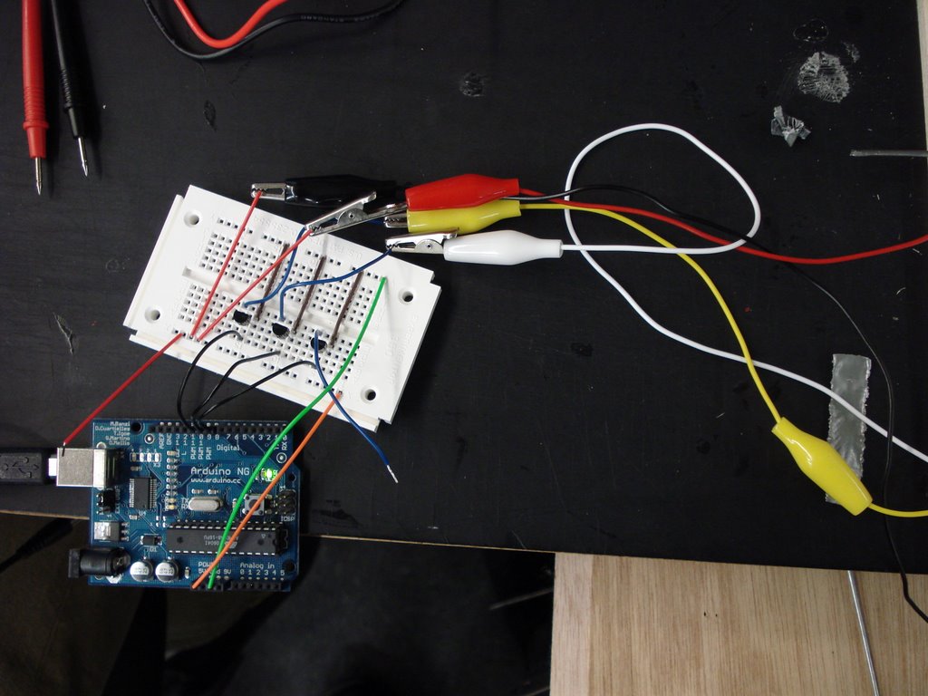

photo of the arduino board and output setups.
also take a peek at this link to a video showing the attempt at 3 simultaneous outputs (flexinol) trough the arduino board using some silly song on gil's totally sweet, new computer. yeah!
on a more serious note- our failure to successfully trip 3 outputs simultaneously has to do with the power distribution limits of the arduino board. we are currently looking for an exterior power source independent of the arduino which will plug directly into the bread board and distribute power to each output channel. it's going to be killer- along with a new source code on maxmsp jitter which will tell our little buddy to attack all three positions, or more, in well thought-out strategery! your sound will mess you up... potentially.
Wednesday, October 11, 2006
INSPIRATION: Peel-and-stick electronics
Tuesday, October 10, 2006
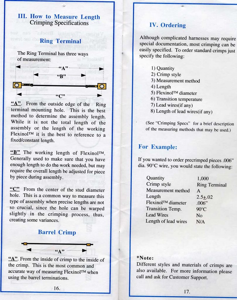
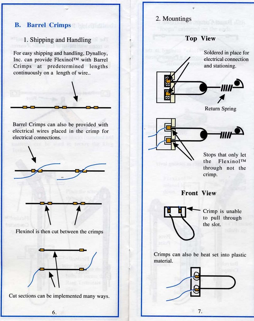
Flexinol Crimping Instructions Part 2


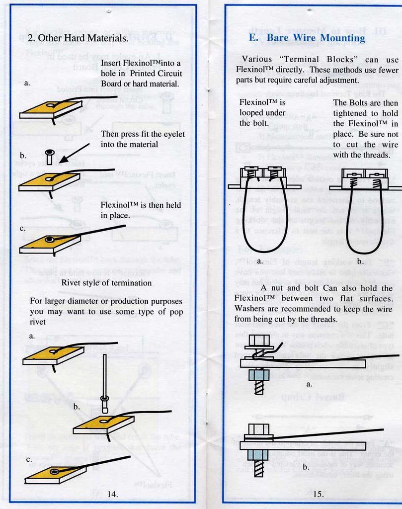
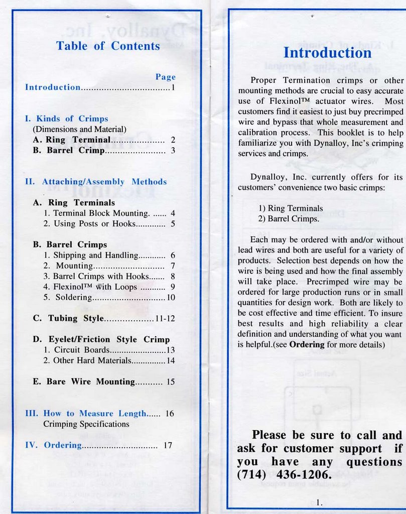
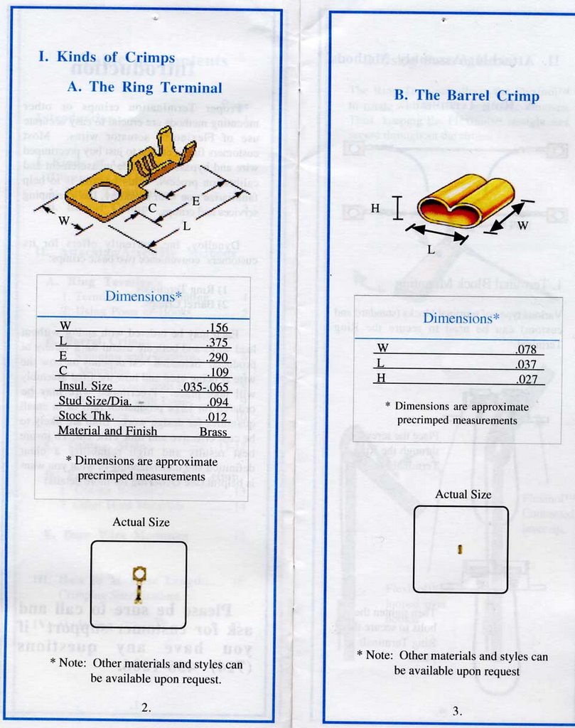
Flexinol Crimping Instructions Part 1

_transistor test
here are the contents of our transistor test. we found one that ramps the voltage higher than the one recommended in prototype01. beware!
///////////////////////////////////////////////////////////////
///transistor test
//mps2222a 3.84V
//2n3904 [prototype01] 3.15V
///////////////////////////////////////////////////////////////
//2n3906 nogood
//mpf102 hotshit [this will burn you]
//1129012d nogood
//1069015aebc nogood
//1069015a hotshit [this will burn you]
///////////////////////////////////////////////////////////////
///transistor test
//mps2222a 3.84V
//2n3904 [prototype01] 3.15V
///////////////////////////////////////////////////////////////
//2n3906 nogood
//mpf102 hotshit [this will burn you]
//1129012d nogood
//1069015aebc nogood
//1069015a hotshit [this will burn you]
Saturday, October 07, 2006
itp physical computing
ITP_PHYSICAL_COMPUTING
_check this out. has some great resources. sensor wiki. arduino labs. parts [where to buy stuff in nyc.]
_check this out. has some great resources. sensor wiki. arduino labs. parts [where to buy stuff in nyc.]
Tuesday, October 03, 2006
_subscript : prototype02

dealing with the possibilities of physical reactions brought upon by different properties of sound, we must consider numerous parameters. first what is to react, then how it will react.
prototype two is the exploration into the geometries and their kinetic ranges. to what extent will materials such as paper and chipboard move while being acted upon by a one dimensional action- their capabilities in themselves and versus each other.
how do we want this 'living architecture' to move? its reaction is our vision of an intrinsic, personal perception- how do we see sound as participating in space... with people; then, in turn, how do we want others to react to our perception of anticipated reactions. user creates sound simultaneously- we create possible reactions in physical, mechanical form- coinciding, is the manifestation of a directed interaction. ironic question posed: what are the unexpected changes?
Tuesday, September 26, 2006
arduiiiiiiiiiino
CUSH_johnson,morris,alayyoubi
Johnson, Morris, Alayyoubi
Living Architecture: Responsive Kinetic Systems Lab
GSAPP fall 2006
RESEARCH PROPOSAL v_1.0
9.26.06
AGENDA
_Element We intend to explore the spatial and structural potential of the responsive kinetic systems of mutational floor elements
_Movement We intend to research and produce a true responsive kinetic system that does indeed move as well as change physical form and volume by transforming from the floor plane into a 3-dimensional element.
_Space Our responsive kinetic system will not be limited to surface transformation, but will affect the spatial and volumetric characteristics of the immediate environment in response to human activity and occupation. This study will focus on interior rather than exterior conditions.
_Realization To fully explore comprehend the implications of a such a research project, it is essential that the physical construction be realized at full scale. We have thus decided to limit the scope of this investigation to the human scale.
_Materiality We intend to explore not only the unconventional use of conventional materials, as well as unconventional materials themselves. The material, particular that which comes in physical contact with people, is the experiential interface, and will therefore be a large focus for this investigation.
PROPOSAL
The “use” of physical space most often requires an active experience. Space often simply becomes a repository for furniture and other effects, and frequently is “used” only at by the behavior and activities of the inhabitant. We intend to explore the possibilities of an passive occupation of space, that is to say, a space which responds to presence of its occupants by transforming itself into functional elements. While the information detected and read by sensors embedded in the space will vary depending on the type of space and different human characteristics, we will be limiting our investigation to the exploration of what and how the space will passively transform itself. We will be using a simple infrared sensor as “binary” input device that detect the presence or absence of an inhabitant, allowing us to focus our resources primarily on the materials and implementation of the output function of the system.
By focusing on output potential, we intend to explore an array of different types of actuators, ranging from servo motors to pneumatics. This portion of the research will test the feasibility and functionality of the different actuators in order to find the most efficient method to transform the surface of the floor. We will simultaneously explore the potential of different materials to act as the interface between the occupant and the mechanism. These materials will include silicon sheets, cast silicon, flexible wood veneers, and a variety of textiles.
Imagine an expansive and open space such as a gallery whose floor plane would only be interrupted when the floor itself detected that an occupant needed to sit; at which point a mass would emerge from the floor to accommodate the need to rest.The goal of this research is to develop a component of a spatial system that, upon detecting the presence of an occupant, will transform, or “grow”, itself into a usable furniture element. The objective is to create a comfortable and functional sofa-type element that will rise from the floor when needed, and recede back into the floor when the occupant rises and walks away. We find this intriguing and fascinating as an exercise of “making something from nothing”.
RESOURCES
www.materialconnexion.com/
_subscript: gil akos. rodrigo piwonka. alan tansey. elliott robert voth.
//_research agenda
//_COMMON ARCHITECTURAL ELEMENT
The architectural element of exploration for subscript will be surfaces, primarily vertical but may grow into elements that inhabit multiple planar fields.
//_MOVEMENT
Movement of the subscript system will consist of an organization of sensors and outputs that have individually “dumb” responsive reactions, but originate from highly tuned audio inputs. The system will respond according to multiple audio properties [such as wave frequency, amplitude, vibration] within unitized embedded elements that are interconnected. Although this relies upon a precise analysis of input, the output of the system is the main direction of subscript. [subscript is confident in its abilities to capture and tune audio input through MAX/MSP/JITTER.]
//_SPATIAL IMPACT
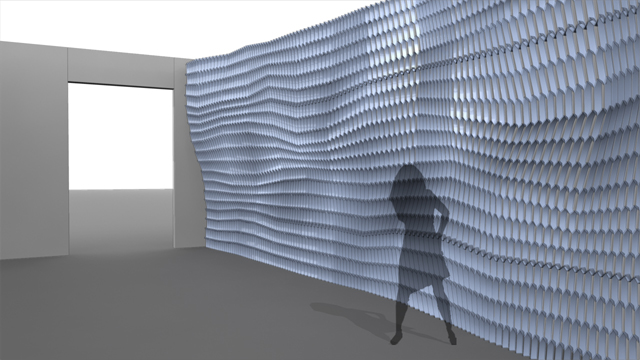
The subscript environment strives for full immersion and response. Its surfaces will be kinetic altering its apertures and surface extension through linear actuated conversion. The surface will not be defined by the planarity of a wall, floor, or ceiling but will be continuous and differentiated in form and reaction (sound reflection).
//_REALIZATION
subscript intends to build and install the final result. subscript will use all tools at their disposal to realize the final element, including other integrative software such as MAX/MSP/JITTER, generative components, and Maya. In addition to physical production, subscript will not be limited by contributions from external software; these tools will be used as additive enhancers of and for performance of the project.
//_research topic proposal
//_output
The primary research topic undertaken by subscript will be within the topic of output. Initial plans for prototyping areas include aperture, linear movement conversion, and topical extension. Output will also be, in some circumstances, the input of the physical reactions to sound and its reflection from the installation.
//_COMMON ARCHITECTURAL ELEMENT
The architectural element of exploration for subscript will be surfaces, primarily vertical but may grow into elements that inhabit multiple planar fields.
//_MOVEMENT
Movement of the subscript system will consist of an organization of sensors and outputs that have individually “dumb” responsive reactions, but originate from highly tuned audio inputs. The system will respond according to multiple audio properties [such as wave frequency, amplitude, vibration] within unitized embedded elements that are interconnected. Although this relies upon a precise analysis of input, the output of the system is the main direction of subscript. [subscript is confident in its abilities to capture and tune audio input through MAX/MSP/JITTER.]
//_SPATIAL IMPACT
The subscript environment strives for full immersion and response. Its surfaces will be kinetic altering its apertures and surface extension through linear actuated conversion. The surface will not be defined by the planarity of a wall, floor, or ceiling but will be continuous and differentiated in form and reaction (sound reflection).
//_REALIZATION
subscript intends to build and install the final result. subscript will use all tools at their disposal to realize the final element, including other integrative software such as MAX/MSP/JITTER, generative components, and Maya. In addition to physical production, subscript will not be limited by contributions from external software; these tools will be used as additive enhancers of and for performance of the project.
//_research topic proposal
//_output
The primary research topic undertaken by subscript will be within the topic of output. Initial plans for prototyping areas include aperture, linear movement conversion, and topical extension. Output will also be, in some circumstances, the input of the physical reactions to sound and its reflection from the installation.
Monday, September 25, 2006
ResearchAgenda_v1.0_Group 9_ Richard, Kirk, Yen
Slip Space
Kirk+Yen+Richard
ResearchAgenda _v1.0
Architectural Element
We will try to create a variation on the ceiling grid that can be dynamic and able to fluctuate patterns.
Movement
Limiting ourselves to the contraction and extension of the Flexonal wire, we will try to create a system that allows non-linear movement
Environmental Impact
A series of physical deformations and realignment of elements within a closed system to create an impact on the quality of light within a space.
Realization
We will build a series of physical models exploring different material, exploiting their physical characteristics to work in a system of our design.
ResearchTopic _v1.0
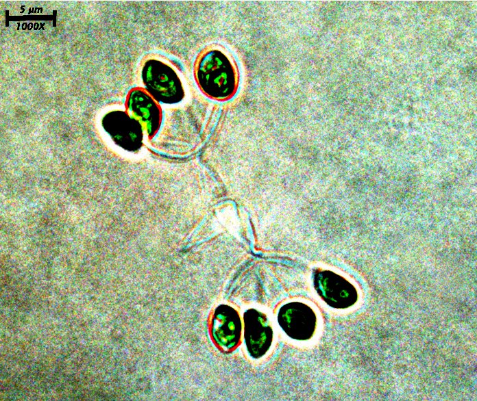
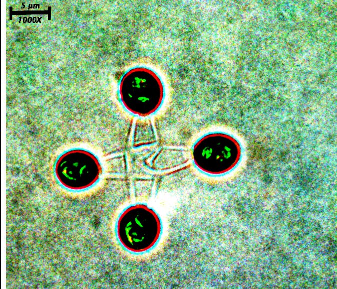
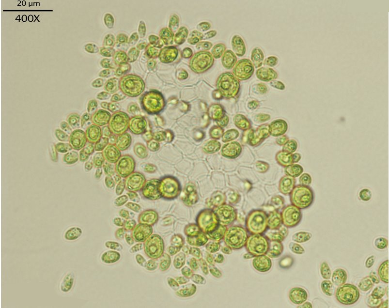
We intend to focus our research in on the output of a system. Looking at algae formation and taking osmotic pressure as a point of departure, we are trying to look at how a series of semi-rigid bodies of various sizes will respond and redistribute itself when agitated into non-determinate movement.
Potential
Lighting, Architectural components, Boundary of Space ( ex. Pattern of wall.) .etc.
The investigation of this application could be an interesting contribution to kinetic architecture by studying a system which has a rigid internal structure, but that still allows for flexibility and free form movement that responds to human interaction.
Wednesday, September 20, 2006
Google Video

Tuesday, September 19, 2006
Reference: Article about art and technology
Assignment: Research Proposal
Assignment: Prototype 1
![]()